
 USA
USA English
 日本語
日本語 中文简体
中文简体
Content
Carrier Tape vs Cover Tape: What Actually Separates Them
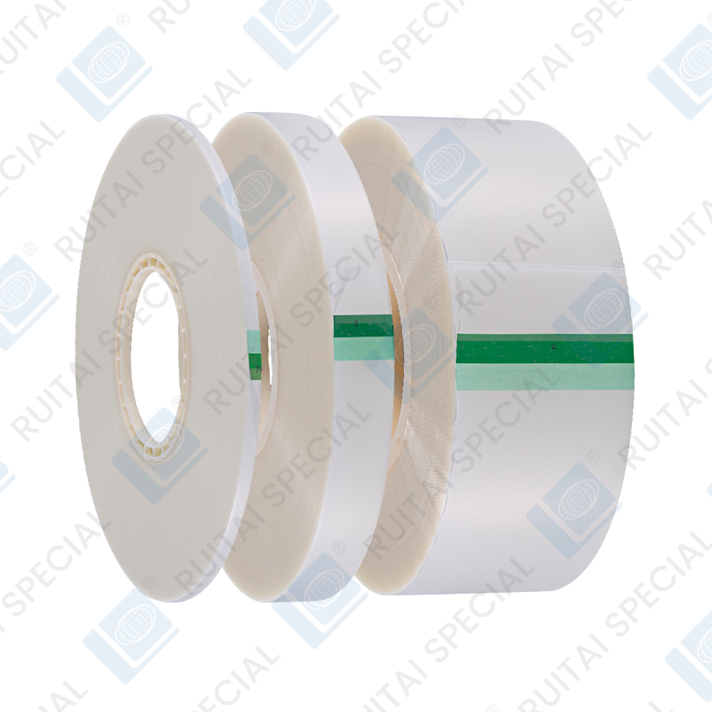
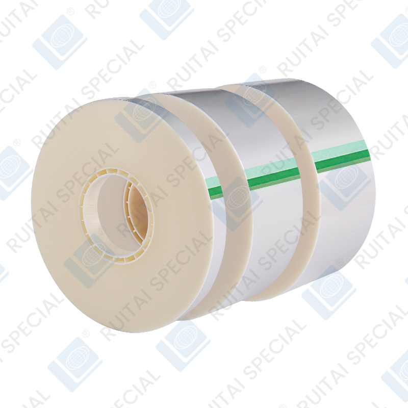
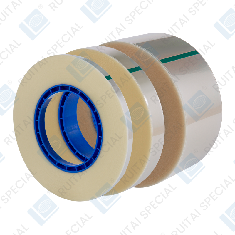
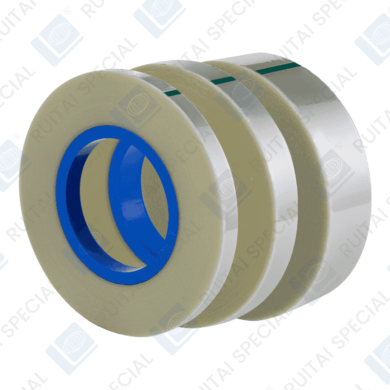
Carrier tape and cover tape are two different layers of the same packaging system, not competing products. Carrier tape is the base strip with molded pockets that hold each component, while cover tape is the thin film heat-sealed on top to keep parts locked in place during transport and pick-and-place feeding. Confusing the two in a spec sheet is one of the most common sourcing mistakes for buyers new to SMT packaging.
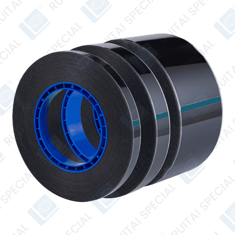
Carrier tape is typically made from black conductive polystyrene, clear PS, or PC/PET blends, with pocket dimensions and pitch matched to the component's footprint — sizes range from 8mm tape for small passives up to 44mm or wider for connectors and larger modules. Cover tape is usually a peelable polyester film, chosen for a specific peel force range so that pick-and-place equipment can remove it cleanly without dislodging or damaging the part underneath.
| Property | Carrier Tape | Cover Tape |
|---|---|---|
| Function | Holds and positions each component | Seals pockets and retains parts |
| Typical material | Polystyrene, PC, PET | Polyester film, heat-seal coated |
| Width range | 8mm–56mm+ | Matched to carrier tape width minus edge margin |
| Key spec | Pocket size, pitch, surface resistivity | Peel force (typically 10–70g) |
Embossed Carrier Tape vs Paper Carrier Tape
Embossed carrier tape is used for larger or taller components, while paper carrier tape is reserved for small, flat, uniform parts like chip resistors and capacitors. The distinction comes down to how the pockets are formed. Embossed tape is heat-formed from a continuous plastic sheet into deep, precisely shaped cavities, which makes it suitable for components with height, irregular shapes, or sensitivity to static — including ICs, connectors, and transistors.
Paper carrier tape is built by die-punching pockets into a base paper layer and laminating a second paper layer beneath it to form the pocket floor. It is more economical for high-volume passive components under roughly 0201 to 0805 case sizes, but it cannot hold taller or heavier parts without pocket collapse or component tilt during high-speed placement.
- Embossed tape: better dimensional stability, supports ESD-safe formulations, standard for ICs and larger discretes
- Paper tape: lower cost per reel, limited to small passive components, not typically available in conductive or ESD grades
- Component height under about 0.8mm generally allows either option; taller parts require embossed tape
How Tape and Reel Packaging Works
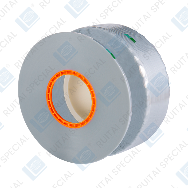
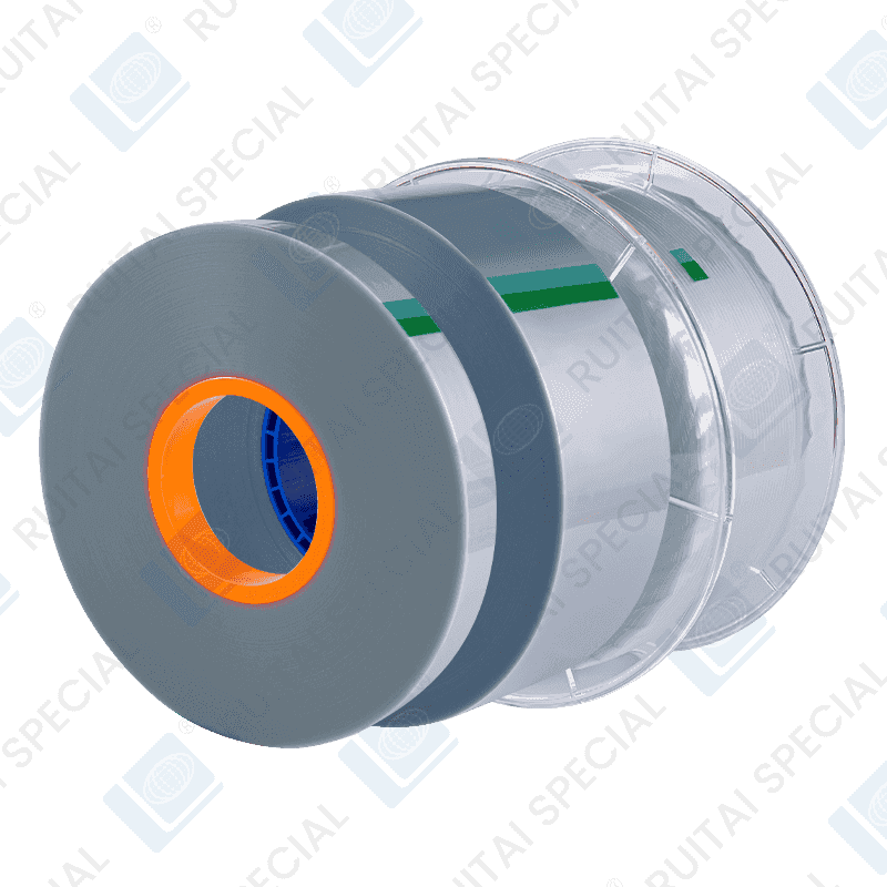
Tape and reel packaging feeds components into automated placement equipment through a fixed sequence: components are dropped into carrier tape pockets, cover tape is heat- or pressure-sealed across the top, the assembled tape is wound onto a plastic reel, and the reel is sealed in a moisture barrier bag with desiccant before shipping. The pocket spacing (pitch) and sprocket holes along the tape edge are standardized so the reel can be loaded directly onto a feeder without any repackaging.
During SMT assembly, the pick-and-place machine indexes the tape forward, peels back the cover tape at a controlled angle just ahead of the pickup point, and a vacuum nozzle lifts the component out of the pocket. Reel sizes commonly follow EIA-481 standards, with 7-inch and 13-inch reels covering most production volumes and larger reels used for high-run lines to reduce changeover frequency.
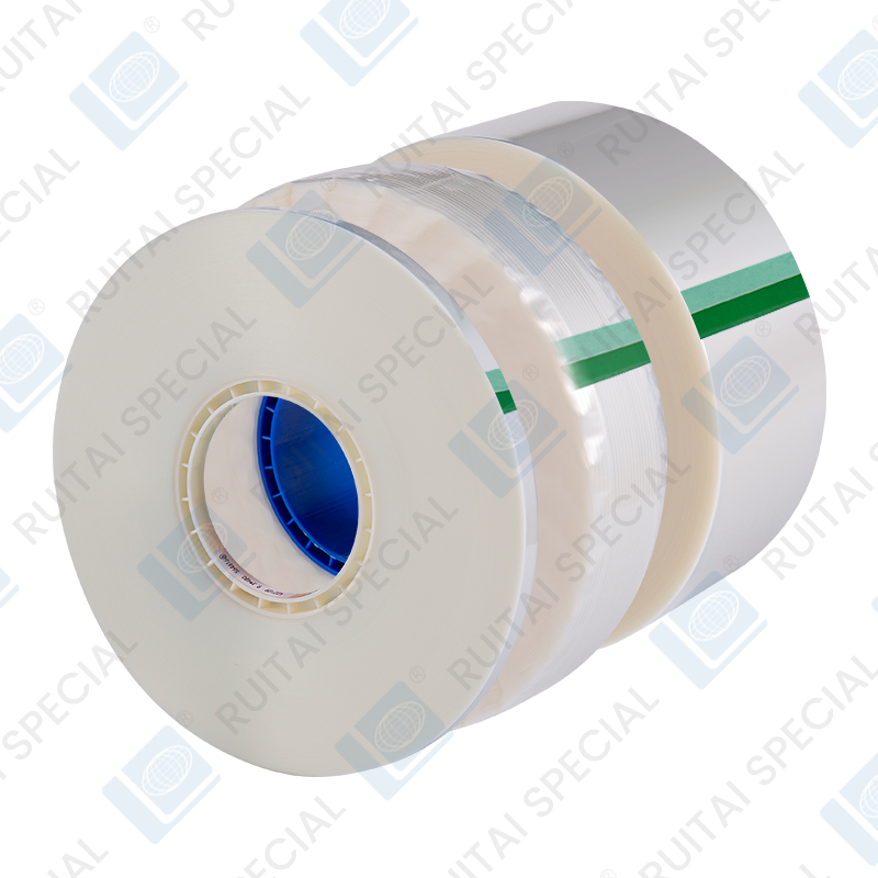
ESD Protection and Moisture Barrier Requirements
Most IC and semiconductor packaging tape is manufactured with surface resistivity in the 10^6 to 10^9 ohm/sq range, which dissipates static charge without creating a fast discharge path that could damage sensitive junctions. Carbon-loaded or intrinsically dissipative resins are used rather than sprayed-on antistatic coatings, since coatings degrade over time and with handling — a detail worth checking when comparing suppliers, as it directly affects long-term ESD performance rather than just the resistivity reading at time of shipment.
Moisture-sensitive devices add a second layer of protection on top of the ESD carrier tape: reels are sealed inside moisture barrier bags rated to MIL-PRF-131 or similar barrier standards, along with desiccant packs and a humidity indicator card. Moisture sensitivity level (MSL) ratings from 1 to 6 determine the maximum allowable floor life once the bag is opened, and devices at MSL 3 or higher typically require baking before assembly if that floor life is exceeded.
- ESD carrier tape: surface resistivity 10^6–10^9 ohm/sq, tested per EIA-541 or ANSI/ESD S541
- Moisture barrier bags: water vapor transmission rate typically under 0.02 g/100in²/24hr
- Desiccant and humidity indicator cards packed inside every sealed moisture barrier bag per J-STD-033 handling guidelines
Selecting Packaging Materials for a Given Component
The right combination of carrier tape, cover tape, and reel depends on three variables: component dimensions, sensitivity to static discharge, and moisture sensitivity level. A 0402 resistor with no static sensitivity can ship on plain paper carrier tape with standard cover tape and no barrier bag. A moisture-sensitive IC in a fine-pitch package needs embossed conductive carrier tape, peelable cover tape rated for the specific pick force of the placement line, and a fully sealed moisture barrier bag with desiccant matched to the reel volume.
Getting the peel force wrong on cover tape is a frequent but avoidable defect source: too high, and the placement machine can pull the component out of position while peeling; too low, and parts can shift or fall out in transit before they ever reach the feeder. Matching peel force to the specific placement equipment's peel angle and speed settings — rather than defaulting to a generic mid-range spec — reduces pickup errors on high-speed lines.